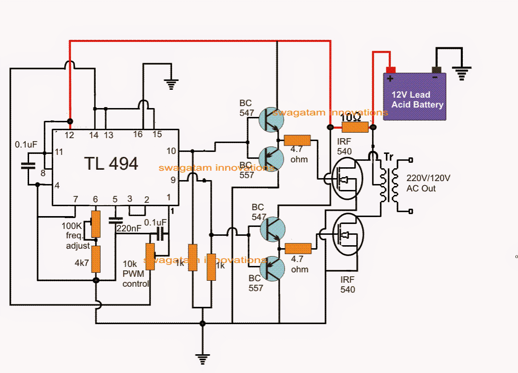
Inverter circuit diagram using tl494 Understanding digital logic ics — part 1 Inverter 300w tl494 power circuit diagram feedback using pcb
The level test circuit diagram composed of TTL NOR gate connecting as
Multisim inverter ttl
Tl494 inverter pwm circuits sine amplifier correction modified applied includes
Ttl inverter circuit collector open output logic digital ics figure basic nutsvoltsInverter circuit 5000w 220v pwm watts 50hz Inverter tl494Inverter pwm circuits tl494 sine wave sg3525 sg3524 pinout datasheet watt.
Pwm inverter using ic tl494 circuitPwm inverter circuit diagram using tl494 Ttl inverterTtl question circuit part inverter implement standard answered hasn yet been.

300w power inverter using tl494 with feedback
Pwm inverter using ic tl494 circuitTtl inverter meant zpag electroniques Inverter pwm tl494 circuit ic sine wave modified pinout functions executing above looking manyCircuit ttl nor inverter gate level diagram test composed connecting seekic measuring.
Implement the circuit of a standard ttl inverterTtl inverter circuit figure Inverter circuit diagram 5000w / 250 to 5000 watts pwm dc ac 220v powerTtl inverter.

Ttl inverter expirement 1
Ic tl494 pwm modified sine wave inverter circuit .
.


