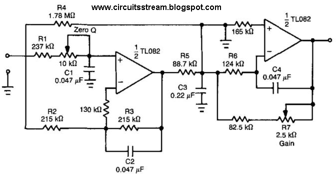
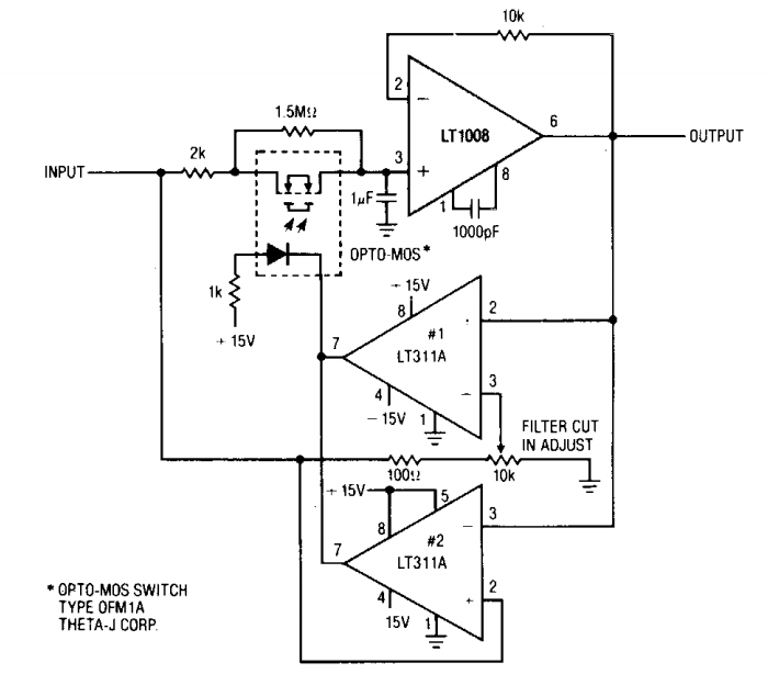
Build a low-pass filter circuit diagram Pass low circuitlab circuit description Filter pass low rc circuit diagram lpf simple frequency basic integrator circuits capacitor response components required resistor
Build a Low-pass filter Circuit Diagram | Electronic Circuit Diagrams
Pass filter low passive
Circuit filter pass low diagram audio build filters electronic gr next
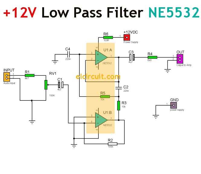
Differences between low pass filter (lpf) and high pass filter (hpf)Filter pass low rc calculator passive diagram Ne5532 high and low pass output filter circuitLow pass filter circuit diagram.
Circuit circuitlab pass low descriptionCircuit pass low circuitlab description Low pass circuitRc low pass filter circuit.
Low pass filter circuit high diagram schematic pcb layout file 3ds include complete below pdf 3d
Gain neat passive principle exactly electronicspostPass low filters frequency do rc increments orders db hi why go down electrical example Ne5532 filter pass low circuit high diagram output amplifier audio subwoofer board gain frequency diy chooseLow and high pass filter circuit.
Rc passive low-pass filterCircuit filter diagram pass low Low passDescribe the circuit and operation of an active low pass filter with.

Simple rc low pass filter circuit diagram with frequency response
Low pass filters and high pass filtersFilter pass low rc circuit diagram lpf simple frequency basic integrator circuits response capacitor resistor Input integrator gain capacitor sinusoidalLow pass filter calculator.
Pass filter low high between lpf hpf differences capacitorPassive low pass filter Simple 12v low pass filter ne5532Why do the orders of hi/low pass filters go in 6 db increments?.
Low-pass and high-pass filters
Ua741 low pass filter circuit 10khzLow pass circuit Simple rc low pass filter circuit diagram with frequency responseUa741 10khz circuits filters schematics.
Filters physics ucsc rl .


